Recommended Audience: Anybody with an Infrastructure, networking, vSphere, and NSX -V background.
What to expect from this post: Prepping the NSX-T environment for configuring “workload management” in vSphere7 with Kubernetes.
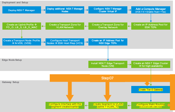
NSX-T Implementation Order > Create Tier-0 Gateway > Configure Static Routing > Create Segment to VLAN > Configure interface with the segment
Here are the high-level implementation steps that we’re going to follow to deploy and configure NSX-T Manager, so we can make it ready for configuring “Workload Management” on vSphere 7.0 to enable Tanzu Kubernetes Grid.
Create Tier-0 Gateway
Tier-0 Gateway is generally a provider-owned gateway that can support static or dynamic routing such as BGP to connect to all the uplinks for the North-South connectivity. This is the only gateway that provides the services between the logical and physical networks. For more details, refer to the NSX-T Architecture post.
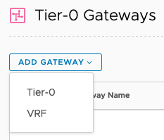
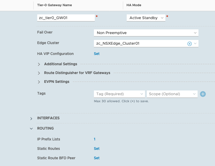
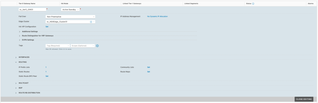
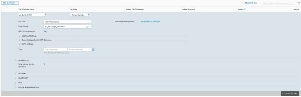
Click on Networking (top-menu) > click on Tier-0 Gateways (left-menu) > click on “ADD GATEWAY” > select Tier-0 > Provide a name > HA mode: Active-Standby > leave failover as Non Preemptive > select Edge Cluster as zc_NSXEdge_Cluster01 > Click Save.
Configure Static Routing to the uplink
A static route will connect the Tier-0 Gateway to the VLAN uplink. For more details on North-South connectivity, please refer to the NSX Architecture post.
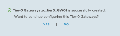
Now, click on YES to configure the Tier-0 Gateway > Expand Routing > Click Set under Static Routes
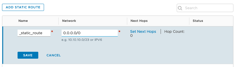
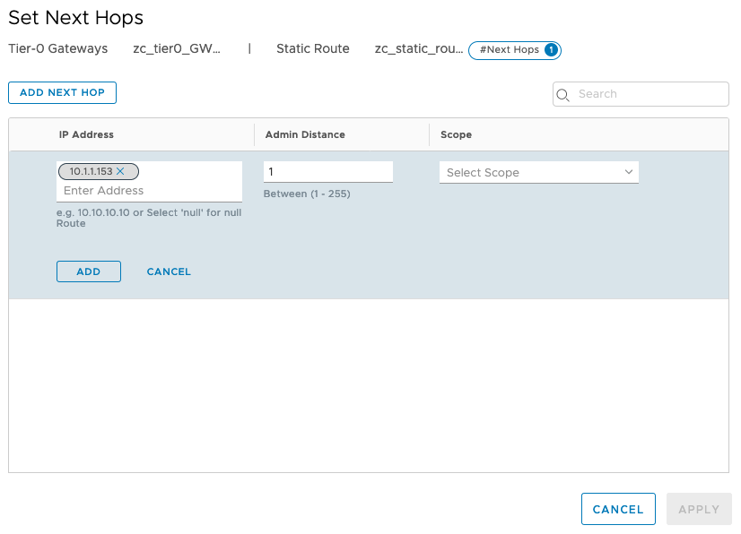
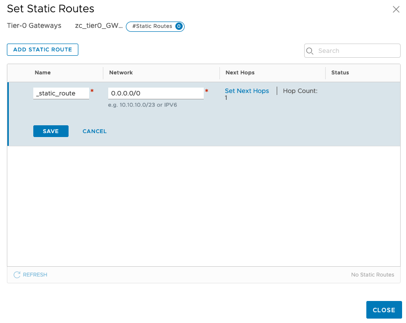
Click on Add Static Route > provide a name > under Network, enter 0.0.0.0/0 > click Next Hop > enter your default gateway (in my case it is 10.1.1.153) > click Add Next Hop > click ADD > click Apply
Click Save > click Close > click Close Editing
Create a Segment to connect to the uplink (VLAN)
Segments are layer 2 broadcast domains to which VMs or transport nodes or NSX Edge nodes can be connected to provide L2 communication. Each segment will be assigned with a VNI, which is similar to VLAN ID. For more details refer to the NSX-T Architecture post. Here, we’re creating a segment to connect the Tier-0 Gateway that’s created earlier to the uplink on VLAN 0.
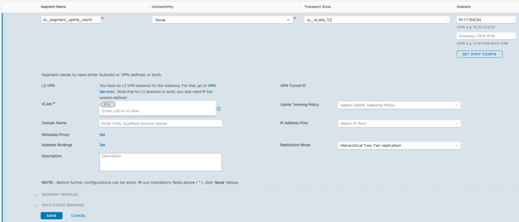
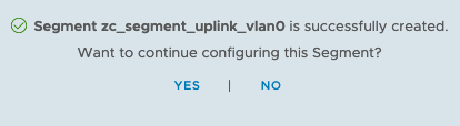
Click on Networking (top-menu) > click on Segments (left-menu) > click on “ADD SEGMENT” > Provide a name > leave Connectivity as none > for Transport Zone, select zc_VLAN_TZ > for subnet, provide an IP address in the same subnet as your default gateway > For VLAN, specify a VLAN for this segment, in my case its VLAN 0 and click SAVE. When prompted to continue for configuring the segment, click NO.
Configure the Tier-0 Gateway’s interface with the segment created earlier
This will establish the North-South connectivity between Tier-0 Gateway and the default gateway by connecting the Tier-0 GW’s interface to the segment’s interface.
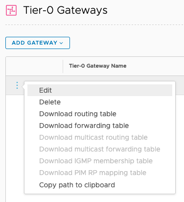
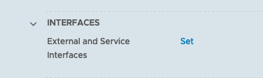
Click on Networking (top-menu) > click on Tier-0 Gateways (left-menu) > in the middle section, click on the three dots and click on Edit > expand Interfaces and click Set.
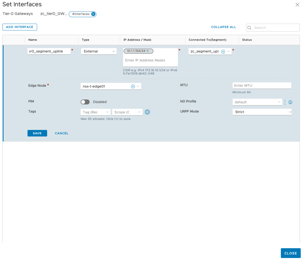
Click on Add Interface > provide a name > leave the Type as External > under IP Address/Mask, type 10.1.1.154/24 (IP address on VLAN 0 to forward to the default gateway) > under Connect TO (Segment), click on the drop-down menu and select the segment created earlier > under Edge Node, select the nix-t-edge01 Node created > click Save > click CLOSE > click CLOSE EDITING.
Make sure the status of the Tier-0 Gateway is success and that concludes the NST-T configuration necessary for configuring Workload Management for vSphere 7 with Kubernetes.